-Photoroom.avif)


What Mechanical Layout Really Means on an MEP Project (HVAC, Ductwork & Piping)
What Mechanical Layout Actually Covers in the Field
In MEP construction, mechanical layout is the process of translating HVAC and piping design drawings into precise, buildable locations in the field. It defines exactly where every mechanical system will be installed in three-dimensional space—horizontally, vertically, and in relation to structure and other trades.
Unlike high-level design drawings, mechanical layout focuses on installation-level accuracy: elevations, offsets, hanger locations, penetrations, and equipment positioning. This is the step that connects coordinated BIM models to real-world construction.
Mechanical layout typically includes:
HVAC Layout — Positioning Air Systems in Three-Dimensional Space
Defines where air systems physically live in the building:
- Duct centerlines and routing paths
- Elevations and vertical offsets
- VAV boxes, fan coils, diffusers, and grilles
- Hanger point locations
- Wall and slab penetrations
- Equipment pads and clearances
HVAC layout ensures airflow paths fit within ceiling spaces, avoid structural conflicts, and maintain access for maintenance.
Ductwork Layout — Geometry, Coordination, and Where Conflicts Concentrate
Focuses specifically on the geometry of duct systems:
- Main trunks and branch runs
- Transitions, elbows, and takeoffs
- Coordination around beams and structure
- Required clearances from lighting, fire protection, and cable trays
- Vertical drops and risers
Poor ductwork layout is one of the most common causes of ceiling clashes and late-stage field rework. HVAC Layout
Defines where air systems physically live in the building:
- Duct centerlines and routing paths
- Elevations and vertical offsets
- VAV boxes, fan coils, diffusers, and grilles
- Hanger point locations
- Wall and slab penetrations
- Equipment pads and clearances
HVAC layout ensures airflow paths fit within ceiling spaces, avoid structural conflicts, and maintain access for maintenance.
Ductwork Layout
Focuses specifically on the geometry of duct systems:
- Main trunks and branch runs
- Transitions, elbows, and takeoffs
- Coordination around beams and structure
- Required clearances from lighting, fire protection, and cable trays
- Vertical drops and risers
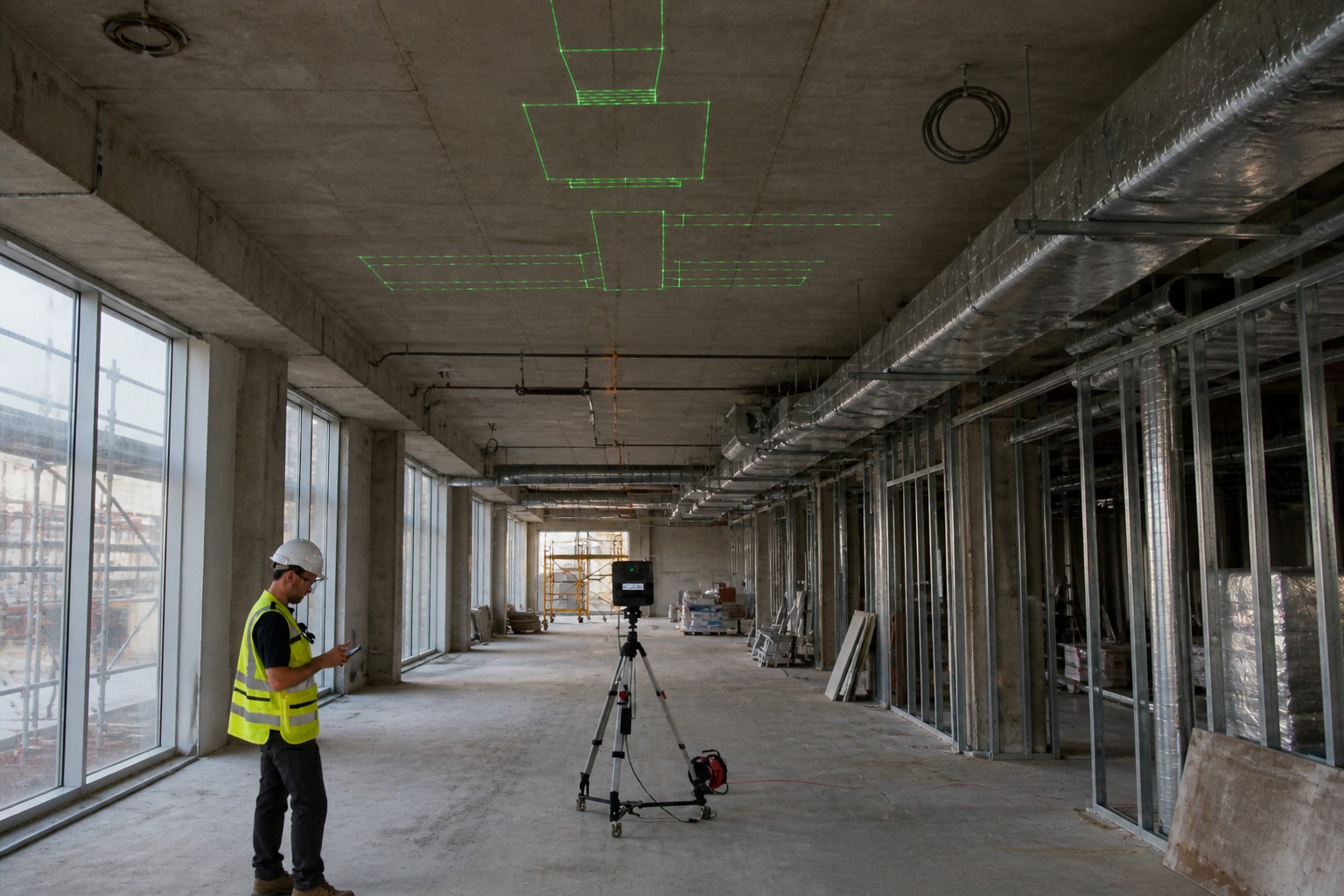
Poor ductwork layout is one of the most common causes of ceiling clashes and late-stage field rework.Mep Contractors using digital layout tools can project duct geometry directly from coordinated models onto the jobsite surface — making clashes visible before installation begins, at full scale, without manual measurement.

Mechanical Piping Layout — Routing, Slope, and Coordination Through Tight Corridors
Controls how mechanical and plumbing pipes move through the building:
- Pipe routing and elevations
- Required slopes for drainage systems
- Valve stations and cleanouts
- Support and hanger locations
- Insulation and clearance requirements
- Coordination through tight corridors and shafts
Accurate piping layout is critical for maintaining flow, meeting code requirements, and avoiding conflicts with ductwork and electrical systems.
Mechanical Equipment Layout — Placement, Clearance, and Downstream Dependencies
Defines placement of major mechanical components:
- AHUs, RTUs, pumps, boilers, and chillers
- Housekeeping pads and anchoring points
- Service access zones
- Maintenance clearance envelopes
- Connection points to duct and piping systems
Equipment layout errors often cascade into major downstream rerouting if discovered late.
In short, mechanical layout is where design becomes construction reality. It determines whether HVAC and piping systems install smoothly—or whether crews spend days reworking conflicts in ceilings and mechanical rooms.
This is also where modern digital tools—coordinated BIM models, reality capture, and BIM-to-field layout—deliver the most value: by giving installers exact locations directly from coordinated designs, reducing manual interpretation, and preventing clashes before material is hung.General contractors managing mechanical scope are typically the ones absorbing that rework cost when equipment placement is not verified against the coordinated model before installation begins.
Where Mechanical Layout Breaks Down — The BIM-to-Field Gap
The failure mode in mechanical layout rarely starts with design. Coordination meetings happen, models get reviewed, clashes get resolved — and field conflicts still emerge after material is hung.
The reason is almost always translation. The accuracy that exists in a coordinated BIM model does not survive the move to printed sheets intact. Elevations get interpreted. Offset dimensions get assumed. When a mechanical installer measures from a reference point that has drifted two inches from the model, every downstream hanger location inherits that error. Conflicts that were resolved in the BIM environment reappear in the ceiling because each trade executed from a different version of the layout.
The result is rework — not because design failed, but because the link between the coordinated model and the physical installation location was never made precise enough to hold.
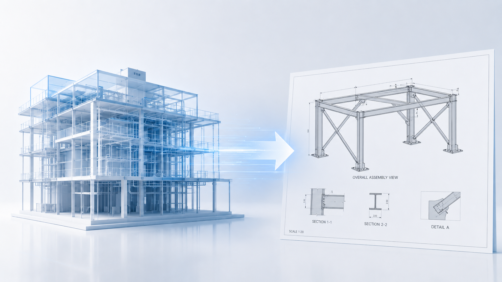
From Coordinated Model to Field Installation — Closing the Mechanical Layout Gap
Solving this requires bringing model accuracy into the field directly, rather than asking installers to reconstruct it from drawings.
BIM-to-field layout tools eliminate the translation step. Duct centerlines, pipe elevations, hanger locations, and equipment pad positions are projected directly onto the work surface from coordinated geometry — giving the installer an exact location rather than a derived one. Penetrations get marked before concrete is poured. Trade conflicts become visible on the slab before material is hung, when they are still cheap to resolve.
For HVAC and piping systems where elevation precision determines whether systems fit within ceiling heights and maintain drainage slopes, the difference between derived layout and model-direct layout is measurable in rework hours and schedule impact.
For MEP contractors and general contractors managing mechanical scope, LightYX supports BIM-to-field mechanical layout workflows, get in touch directly, to discuss your project.