-Photoroom.avif)


What Is MEP in Construction? Layout Challenges and Modern Digital Solutions
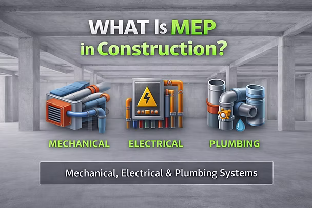
What is MEP in construction?
MEP in building construction refers to Mechanical, Electrical, and Plumbing systems—the building systems that make a structure functional, occupiable, and maintainable (comfort, power, water, drainage, safety, and operations).
You’ll also hear “MEP engineering” or “MEP trades” because these systems are usually designed and coordinated together, they interact constantly and compete for limited space (especially above ceilings and in shafts).
Practical takeaway: the building may “stand” without MEP, but it can’t be occupied, operated, or maintained without it.
This is where execution becomes critical. Even when MEP systems are fully designed and coordinated in BIM, many projects struggle during layout and installation because model information still has to be manually interpreted in the field. LightYX helps bridge this BIM-to-field gap by delivering coordinated model data directly to layout workflows, so MEP systems are installed where they were coordinated—reducing rework and layout-driven delays.
MEP in Building Construction: What’s Included?
1) Mechanical (HVAC) systems
Mechanical typically means HVAC: heating, ventilation, and air conditioning. It includes equipment (AHUs/RTUs, VAVs, fan coils), ductwork, diffusers/grilles, dampers, insulation, and controls tie-ins. Because mechanical systems occupy a large portion of ceiling space, mechanical layout accuracy plays a major role in preventing clashes and rework during installation.
2) Electrical systems
Electrical covers power distribution, lighting, panels/switchboards, conduits, devices, and life-safety connections (often tightly linked with fire alarm and emergency power).Electrical layout must remain tightly coordinated with mechanical and plumbing systems—especially in congested ceiling zones—to avoid field conflicts.
3) Plumbing systems
Plumbing includes domestic water, waste/vent, storm drainage, gas (scope varies by region/team), fixtures, and pipe routing/supports.
Why this matters: many projects see MEP as a major cost and schedule driver; one industry article claims MEP can represent a very large share of total construction cost. (Treat this as a directional benchmark—actual % varies by building type and market.)Because plumbing relies on gravity and tight tolerances, plumbing layout accuracy is especially critical. Small errors often surface later as core drilling, re-sloping, or rerouting.
Why MEP Matters in Construction Projects
[Keyword reinforced contextually: MEP layout challenges]
On many projects, MEP systems represent a major share of construction cost and schedule risk. Poor coordination or inaccurate layout often leads to:
- Rework
- RFIs
- Trade stacking
- Schedule compression late in the project. This is why MEP layout challenges frequently determine whether a project stays on track.
- The Real-World MEP Workflow: How Drawings Become Installed Systems
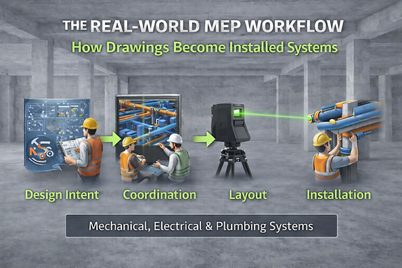
On most building projects, MEP does not move directly from design to installation. Instead, it passes through several coordination and translation stages before anything is physically built. Each step introduces interpretation, handoffs, and potential risk.
A typical real-world MEP workflow looks like this:
1. Design Intent (Engineers)
The process begins with mechanical, electrical, and plumbing engineers producing schematic and design development drawings. These documents define system intent—equipment sizes, general routing, performance requirements, and code compliance—but they are not detailed enough for field installation.
At this stage, layouts are conceptual. Exact elevations, hanger locations, penetrations, and trade-to-trade coordination are usually not finalized.
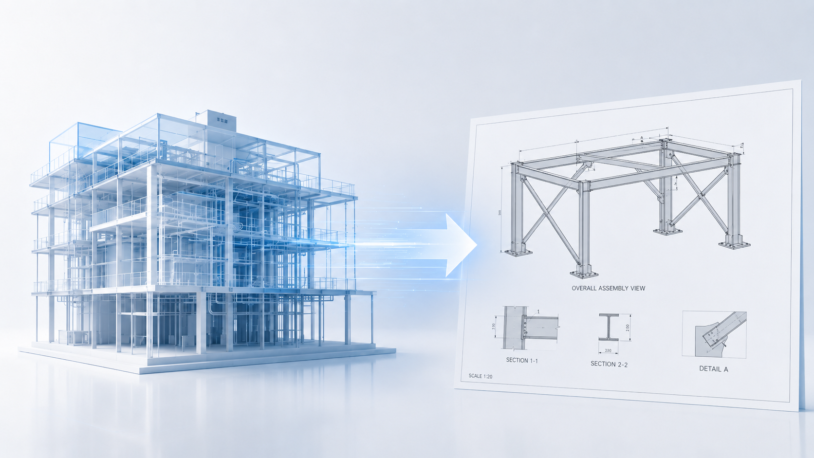
2. Coordination (GC + MEP Trades + VDC/BIM Teams)
Next comes coordination, where general contractors and trade partners combine models and drawings to resolve conflicts between HVAC, piping, electrical, fire protection, and structure.
This phase aligns:
- Duct, pipe, and conduit routing
- Vertical elevations
- Shaft and corridor usage
- Equipment access and maintenance zones
The goal is to produce a coordinated BIM model that all trades can build from. This is where many clashes are discovered—and where major routing decisions are locked in.
3. Detailing & Shop Drawings (Trade Partners / Fabricators)
Once coordination is complete, each trade creates installation-level documentation:
- HVAC spools and duct fabrication drawings
- Pipe spools and valve assemblies
- Sleeve and penetration locations
- Hanger and support details
- Equipment setting drawings
These shop drawings translate the coordinated model into components that can be fabricated and installed. However, they still must be interpreted on site unless connected directly to field layout workflows.
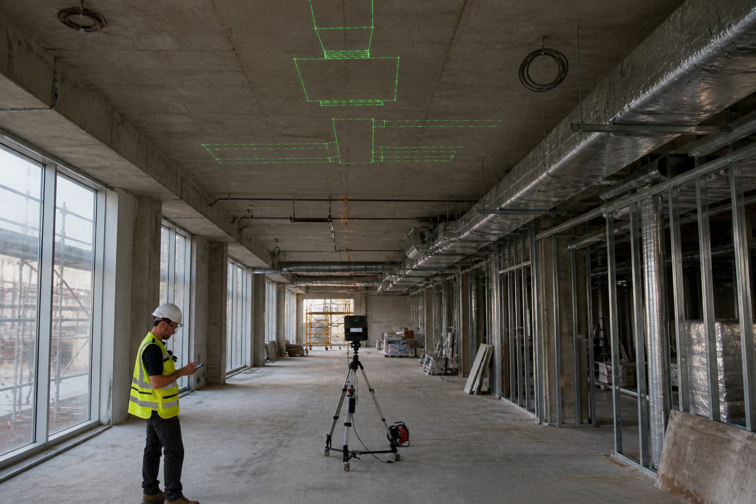
4. Layout (BIM-to-Field Translation)
This is the critical bridge between digital coordination and physical construction.
During layout, coordinated models and shop drawings are converted into real-world reference points on the jobsite:
- Hanger locations
- Sleeve and penetration points
- Equipment footprints
- Pipe and duct routing reference lines
- Fixture and device rough-ins
Traditionally, this step relies on manual measuring, tape, chalk lines, and printed drawings. Any mismatch between drawings and site conditions often surfaces here—after coordination is “complete.”
This is where many projects experience friction: small dimensional errors turn into rerouting, core drilling, or re-sloping once crews begin installing.
Modern BIM-to-field tools and digital layout workflows aim to eliminate this translation gap by delivering coordinated model data directly to the jobsite.
5. Installation (Field Crews)
With layout complete, crews begin rough-in:
- Hanging ductwork
- Installing piping and conduits
- Setting equipment
- Completing inspections
- Closing walls and ceilings
If layout was inaccurate or site conditions were not validated early, this phase quickly turns into field fixes and schedule pressure.
6. As-Builts & Handover (Operations & Maintenance)
Finally, installed conditions are captured and delivered as as-built documentation for owners and facility teams. These records support long-term maintenance, renovations, and operations.
What Mechanical Layout Really Means
In building construction, mechanical layout translates HVAC and piping designs into exact installation locations in the field. It defines where ductwork, mechanical piping, and equipment run above ceilings, through walls, and across floors—while coordinating with structure and other trades.
Mechanical layout typically includes duct routing and elevations, hanger points, equipment placement, penetrations, and service clearances, along with piping paths and valve locations. Because mechanical systems occupy much of the ceiling space, layout accuracy is critical to avoid clashes, rerouting, and rework.
What Electrical Layout Really Means
Electrical layout converts electrical drawings into precise field locations for conduits, panels, lighting, and devices. It determines how power and low-voltage systems move through the building and where fixtures, receptacles, and equipment are installed.
Electrical layout must stay tightly coordinated with HVAC and plumbing—especially in congested ceilings—to maintain clearances and consistent device placement. Accurate layout reduces field adjustments and keeps electrical installation aligned with coordinated BIM models.
What Plumbing Layout Really Means
Plumbing layout defines the exact routing of domestic water, sanitary, vent, and storm systems inside the building. It establishes pipe elevations, slopes, fixture rough-ins, riser locations, and slab or wall penetrations before construction progresses.
Because drainage relies on gravity and tight tolerances, plumbing layout is highly sensitive to accuracy. Proper layout prevents core drilling, re-sloping, and late-stage conflicts with mechanical and structural systems.
These are now perfectly sized to link out to:
Read more: Mechanical Layout in Building Construction
What are the MEP layout challenges (why HVAC installation and piping installation get messy)
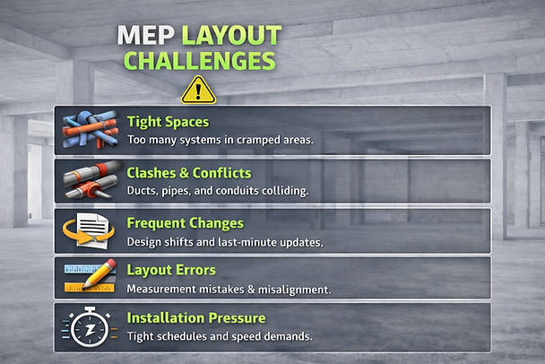
Challenge 1: Too many systems in too little space
The ceiling plenum becomes a “traffic jam”: duct mains, branch ducts, hydronic/chilled water, domestic water, sanitary, vents, cable tray, conduit, fire protection, structural constraints—all stacked in inches. This calls out that MEP systems are highly interdependent and can inflate cost/schedule without careful coordination.
Challenge 2: Clashes (hard and soft) + late discovery
- Hard clashes: pipe through beam; duct through cable tray
- Soft clashes: no access to valves/dampers; insufficient clearance; maintenance conflict
Designing MEP in isolation makes clashes more likely; coordinated design is specifically recommended to prevent location conflicts.
Challenge 3: Changes + version control in the field
A single upstream change (ceiling height, beam depth, equipment selection) can cascade into reroutes across multiple trades. Procore emphasizes structured communication and early coordination to reduce risk.
Challenge 4: Layout accuracy + tolerance stack-up
Even with good drawings, the field reality (as-built structure, embeds, sleeves, penetration locations) can differ. Small offsets turn into hours of rework when you’re hanging long duct runs or threading pipes through tight corridors.
Challenge 5: Productivity pressure (install speed vs. correctness)
MEP is labor-heavy. If layout is slow or wrong, you get:
- rework
- RFIs
- schedule compression
- trade stacking and congestion
Modern digital solutions for MEP layout (what actually reduces risk)
1) BIM coordination + clash detection (before you install)
BIM improves accuracy and reduces coordination errors; coordinated models help teams see conflicts early.
Best practice: don’t just “run clashes once.” Run clashes:
- at DD milestone
- before procurement/fabrication
- before rough-in
- when major changes happen
2) Reality capture technology (scan the jobsite, not just the drawings)
Reality capture is the process of collecting real-world measurements and imagery to recreate a site in digital 3D for existing conditions, planning, and QA.
Common reality capture methods:
- 360 photos / walkthroughs
- photogrammetry
- LiDAR / laser scanning (point clouds)
Why MEP teams care: because you can compare design vs. reality (structure, sleeves, penetrations, installed work) and catch problems early.
3) Scan-to-BIM (turn point clouds into usable models)
Scan-to-BIM uses reality capture data to create or update a model that reflects what’s actually built—especially useful in renovations, TI, hospitals, and anywhere “as-builts” are unreliable.
4) Digital field layout (BIM-to-field for MEP install)
After coordination, you still need fast, accurate layout onsite:
- hanger points
- sleeve/penetration locations
- equipment footprints
- corridor/ceiling routing reference points
Digital layout methods vary (total station workflows, layout from coordinated model, and newer projection-based workflows). The consistent theme is the same: reduce manual measuring and translation errors.
5) QA/QC loops that don’t wait until the end
Reality capture + coordinated model lets teams verify:
- rough-in accuracy
- elevation compliance
- clearance/access
- “did we install what we coordinated?”
Autodesk explicitly frames reality capture as supporting existing conditions, planning, and quality assurance in construction.
Conclusion
MEP systems are the backbone of any building—but they are also among the most complex scopes to coordinate and install. Mechanical, electrical, and plumbing trades operate in tight spaces, rely on precise elevations and tolerances, and are often impacted by late changes and field constraints.
While BIM has improved coordination and clash detection upstream, many projects still experience issues when coordinated models are translated into field layout. Manual interpretation at this stage remains a common source of rework, delays, and installation inefficiencies—especially on MEP-intensive projects.
Closing this gap requires more than coordinated drawings. It requires reliable BIM-to-field workflows that carry design intent through layout and into installation. When layout is accurate and aligned with the coordinated model, MEP teams can install with confidence, reduce field fixes, and keep work moving as planned.
If your MEP projects are coordinated in BIM but still face layout-driven rework in the field, LightYX helps bridge that gap by connecting coordinated model data directly to field layout workflows. Explore LightYX’s MEP layout solutions .
FAQs
What does MEP mean in construction?
MEP means Mechanical, Electrical, and Plumbing—the systems that deliver climate control, power, lighting, water supply, drainage, and other building services.
Why is MEP coordination so difficult?
Because MEP systems are highly interdependent, compete for limited space, and often clash when designed or updated in isolation—especially above ceilings and in shafts.
What is reality capture technology in construction?
Reality capture is the process of collecting real-world measurements/images (including LiDAR and photogrammetry) to recreate a site in digital 3D for existing conditions, planning, and QA.
What are “MEP layout solutions” today?
Modern solutions combine BIM coordination, clash detection, reality capture / scan-to-BIM, and digital field layout to reduce rework and speed installation.