-Photoroom.avif)


What Electrical Layout Really Means in Building Construction
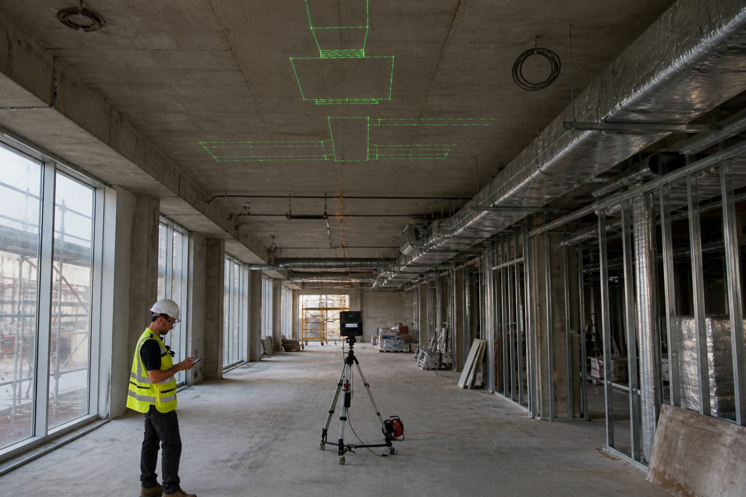
In MEP projects, electrical layout is the process of translating electrical design drawings into exact, install-ready locations inside the building. It defines where power, lighting, and low-voltage systems physically run—across slabs, through walls, above ceilings, and inside shafts.
While electrical drawings show intent, electrical layout focuses on constructability: precise device placement, conduit routing, elevations, penetration points, and coordination with HVAC and plumbing systems, which is where BIM-to-field layout tools eliminate manual interpretation and deliver model-accurate positions directly to the field
What Electrical Layout Covers in MEP Projects
Power Distribution Layout
Defines how electricity moves from service entry to end devices:
- Main switchgear, panels, and subpanels
- Conduit routing and elevations
- Feeder paths through corridors and shafts
- Equipment connection points
- Floor and wall penetrations
- Clearance zones around electrical rooms and panels
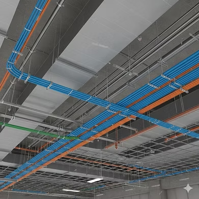
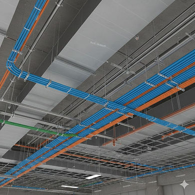
Accurate power layout prevents conflicts with ductwork and piping while ensuring code-required access to panels and equipment — a challenge MEP contractors face daily when routing conduit through congested ceiling spaces on commercial projects.
Lighting Layout
Controls placement and coordination of lighting systems:
- Light fixture locations and spacing
- Ceiling coordination with diffusers, sprinklers, and speakers
- Switching zones and control wiring paths
- Emergency and egress lighting locations
Lighting layout is highly sensitive to ceiling geometry—small shifts in HVAC or structure often require lighting to be reworked unless layouts are tightly coordinated.
Device & Low-Voltage Layout
Covers all building systems beyond primary power:
- Receptacles and floor boxes
- Data, AV, security, and fire alarm devices
- Cable tray routing
- Backboxes and wall rough-ins
- Coordination of device heights and alignments
Poor device layout leads to visible inconsistencies in finished spaces and costly drywall rework.
Electrical Equipment Layout
Defines placement of major electrical assets:
- Transformers, generators, UPS systems
- Electrical rooms and risers
- Required working clearances
- Access paths for installation and maintenance
Mistakes here often impact multiple trades and can force major rerouting late in the project.
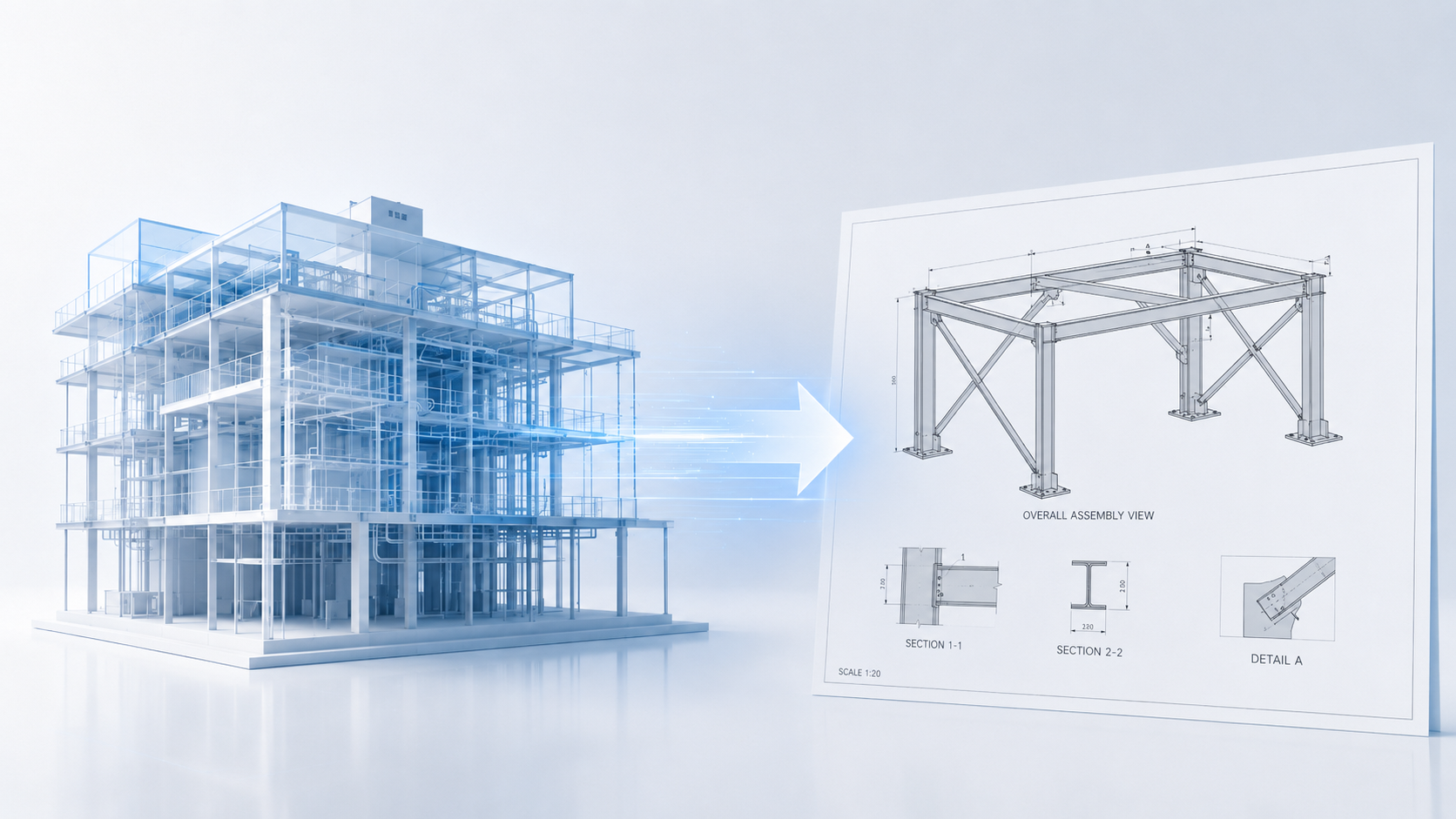
In short, electrical layout determines whether power and systems install cleanly—or whether crews are forced to reroute conduits around ducts, pipes, and structure in the field.
Digital coordination and BIM-to-field workflows reduce interpretation errors by giving electricians precise install points directly from coordinated models — eliminating the manual measurement step that causes most electrical layout conflicts.
Conclusion
For electrical contractors evaluating layout precision on MEP projects, get in touch directly to discuss how LightYX supports field execution workflows.