-Photoroom.avif)


From BIM to Shop Drawings: How Digital Models Become Construction-Ready
In modern construction, almost every major project starts with digital information. Architects, engineers, general contractors, subcontractors, VDC teams, and fabricators all rely on models, drawings, schedules, and data to move a project from design to construction.
But there is still a common misunderstanding in the industry: that the BIM model created during design is automatically ready for fabrication and field installation.
In reality, that is rarely the case.
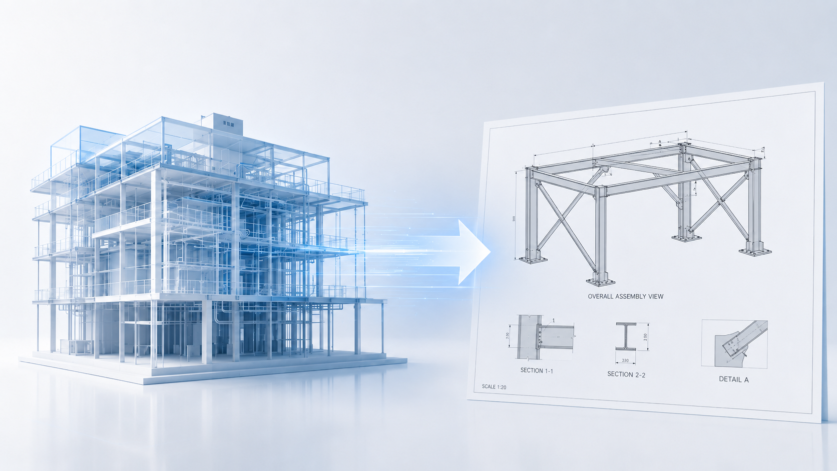
A design BIM model is usually created to communicate design intent, coordination requirements, system locations, and performance expectations. It shows what the building should become. But before a subcontractor can fabricate steel, order ductwork, place hangers, build wall assemblies, install sleeves, or coordinate penetrations, that design information must be translated into something more detailed, trade-specific, and construction-ready.
That transition happens through shop drawings.
Shop drawings are the bridge between the digital design model and the real construction work. They convert BIM information into the precise fabrication, assembly, coordination, and installation details required by the people who actually build the project. Your original article direction is accurate: shop drawings are the critical step between BIM and physical construction, but the article should emphasize that they are not just “paperwork” — they are the point where design intent becomes buildable information.
What Are Shop Drawings?
Shop drawings are project-specific drawings, diagrams, schedules, and other data prepared by the contractor, subcontractor, manufacturer, supplier, or fabricator to illustrate a specific portion of the work. AIA describes shop drawings as documents specially prepared for the work by the contractor to show how part of the work will be implemented. CSI gives a similar definition, describing shop drawings as contractor- or subcontractor-prepared information used to illustrate a portion of the work. (csiresources.org)
In simple terms, design drawings explain what needs to be built. Shop drawings explain how that work will be fabricated, assembled, coordinated, and installed.
That difference is important.
Architectural and engineering drawings may show the location of a steel frame, duct run, ceiling system, wall assembly, or mechanical room. But shop drawings go deeper. They include connection details, fabrication dimensions, material information, sleeve locations, hanger locations, welds, bolts, tolerances, equipment clearances, installation sequencing, and trade-specific coordination details.
For example, a structural design model may show that a steel beam exists in a certain location. The steel shop drawing shows the beam size, plate details, connection geometry, bolt holes, weld symbols, erection marks, and how the member connects to the rest of the structure.
A mechanical design model may show the general route of a duct or pipe. The mechanical shop drawing or fabrication model defines the exact routing, hanger points, sleeves, offsets, spool sections, clearances, and coordination with other systems.
A drywall or interior framing drawing may show wall locations and partition types. A shop drawing can define framing conditions, soffits, curved walls, backing, rough openings, ceiling transitions, and details needed by the field crew.
This is why shop drawings are not just a documentation step. They are a construction translation step.
Why Design Drawings Are Not Enough
Design drawings and BIM models are created by architects and engineers to define the project’s intent. They establish the building’s layout, performance requirements, code compliance, structural systems, MEP systems, and architectural design.
But design intent is not the same as fabrication intent.
A design model may show where a system belongs, but it usually does not include every detail required for manufacturing, purchasing, fabrication, assembly, or installation. It may not include final manufacturer-specific components, actual hanger assemblies, installation tolerances, field constraints, exact penetration locations, or fabrication-ready connection details.
That is where the construction team takes over.
Shop drawings are typically produced by subcontractors, specialty trades, fabricators, VDC teams, or third-party detailers. They are then submitted to the architect, engineer, or design team for review. This review is generally intended to confirm conformance with the design intent and contract documents. It does not usually transfer responsibility for means, methods, sequencing, or fabrication decisions away from the contractor.
This distinction matters because it protects the roles of each party. The design team defines the intent. The contractor and trade partners define the buildable execution. The shop drawing process is where those two worlds are checked against each other before fabrication or installation begins.
The BIM-to-Shop Drawing Transition
BIM has changed how shop drawings are created. In the past, shop drawings were often produced as standalone 2D drafting documents. Today, many shop drawings are generated from coordinated 3D trade models.
This is where the BIM-to-shop drawing transition becomes powerful.
Instead of redrawing everything manually, VDC and trade detailing teams can use BIM models as a starting point. They develop trade-specific models with the information required for coordination, fabrication, procurement, and installation. From those models, they generate shop drawings, spool drawings, sleeve drawings, hanger drawings, embed drawings, panel drawings, and fabrication packages.
However, the BIM model must be developed to the right level of detail and reliability before it can support those uses. That is why LOD — Level of Development — is so important.
Understanding LOD: The Missing Link Between BIM and Shop Drawings
LOD is often misunderstood. It does not simply mean “more detail.” It defines how reliable a model element is for a specific use.
BIMForum’s LOD Specification was created to provide a more detailed interpretation of AIA’s LOD definitions and to help project teams define model element requirements more clearly. (BIM Forum) In other words, LOD helps teams understand what information can be trusted in the model and what that information can be used for.
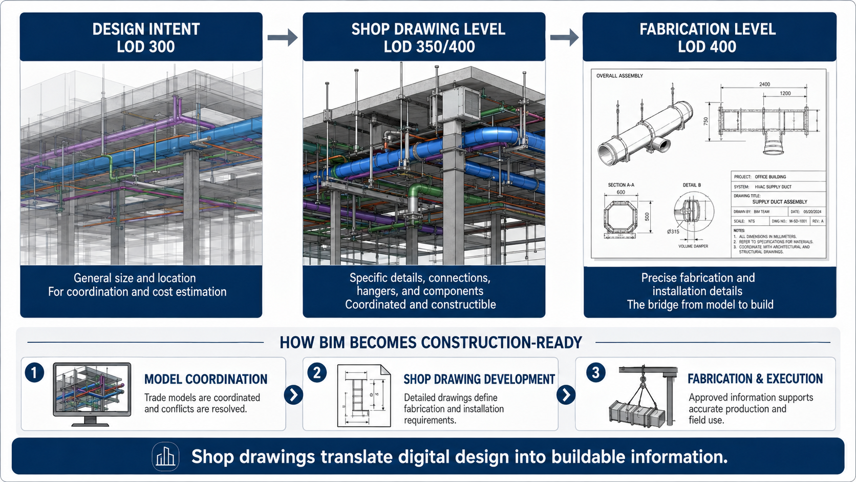
A simplified way to understand the relationship between BIM and shop drawings is:
LOD 300 generally represents design-level information. The element has defined size, shape, location, and orientation, and it can support construction documentation and coordination.
LOD 350 adds more detail about how the element interfaces with other building systems. This is important for coordination because it begins to show supports, connections, clearances, and relationships between trades.
LOD 400 represents fabrication and assembly-level information. At this stage, the model includes the details needed for fabrication, assembly, and installation. Autodesk describes LOD 350 as useful for generating construction documents and shop drawings, while LOD 400 includes specific assemblies and connections suitable for fabrication and assembly.
This distinction is important. Not every construction task requires a full LOD 400 model, but the closer the work gets to fabrication, prefabrication, hanger placement, sleeve coordination, embeds, steel connections, and field installation, the more important high-quality construction-level information becomes.
For many trades, the shop drawing process is where the model moves from general design intent to coordinated, buildable detail.
Why the BIM-to-Shop Drawing Transition Matters
The quality of the BIM-to-shop drawing transition directly affects project cost, schedule, coordination, and rework.
Construction has long struggled with productivity compared with other industries. McKinsey reported that global construction labor productivity grew by only about 1% per year over two decades, compared with 2.8% for the total world economy and 3.6% for manufacturing. (McKinsey & Company) Poor information flow is one reason construction work remains difficult to plan and execute efficiently.
The cost of bad information is significant. A NIST study estimated that inadequate interoperability cost the U.S. capital facilities industry $15.8 billion annually in 2002. More recently, Autodesk and FMI reported that bad data may have caused $88.69 billion in construction rework in 2020 and accounted for about 14% of all rework performed that year.
The Construction Industry Institute has also found that quality deviations resulting in rework, repair, replacement, or redesign can represent a major share of installed project cost. One CII study found that deviations resulting in rework accounted for an average of 12.4% of total installed project cost across nine industrial construction projects. (construction-institute.org)
These numbers point to a clear issue: when construction teams work from incomplete, inconsistent, outdated, or poorly coordinated information, the cost shows up in the field.
Shop drawings help reduce that risk by forcing the project team to answer practical construction questions before work is fabricated or installed:
Where exactly does this component go?
How does it connect?
What material or manufacturer is being used?
Does it clash with another trade?
Can it be fabricated as shown?
Can it be installed safely and efficiently?
Does the field team have enough information to execute the work without guessing?
Shop Drawings as a Coordination Tool
Shop drawings are not only about fabrication. They are also a coordination checkpoint.
On complex projects, multiple trades often need to occupy the same ceiling space, slab zone, wall cavity, shaft, or mechanical room. Ductwork, piping, electrical conduits, sprinkler lines, structural steel, embeds, ceiling systems, and architectural elements all compete for physical space.
The BIM model may show the general location of these systems, but trade coordination requires more detail. Mechanical, electrical, plumbing, fire protection, structural, and architectural teams need to coordinate real dimensions, real installation conditions, and real clearances.
This is where shop drawings and coordinated trade models become essential.
A mechanical contractor may adjust duct routing to avoid a beam. A plumbing contractor may revise pipe routing to avoid a conflict with electrical conduit. A steel fabricator may coordinate connection plates and embeds before fabrication. A drywall contractor may adjust framing and backing details to support equipment, doors, soffits, or ceiling transitions.
In a strong BIM-to-shop drawing workflow, these decisions are made digitally before crews are standing in the field waiting for answers.
Information Requirements: Defining What Needs to Be Delivered
A good BIM-to-shop drawing process depends on clear information requirements. The project team needs to define what information is needed, who is responsible for producing it, when it must be delivered, and what it will be used for.
This is a major theme in ISO 19650-based information management. UK BIM Framework guidance explains that information requirements specify what information is needed and help connect detailed project information back to a higher-level purpose. (UK BIM Framework) The same guidance emphasizes that information requirements should define how and when information is exchanged during the project or asset lifecycle.
This matters because a BIM model without clear information requirements can become confusing. Different teams may assume different levels of reliability. One person may think a model element is suitable for fabrication, while another sees it only as design intent.
For shop drawings, this can create real problems.
If the design model is treated as fabrication-ready when it is not, the trade contractor may rely on incomplete information. If the shop drawing model is not reviewed and coordinated properly, fabrication may start before clashes are resolved. If the wrong version of a drawing is used in the field, crews may install work based on outdated information.
The solution is not just “more BIM.” The solution is better information management: clear responsibility, clear model uses, clear LOD expectations, clear submittal workflows, and controlled information exchange.
Interoperability: Moving Data Between Teams and Tools
Another challenge in the BIM-to-shop drawing transition is interoperability.
Construction projects involve many different software platforms, file formats, stakeholders, and trade-specific workflows. Architects may work in one design environment. Structural engineers may use another. MEP contractors may detail in fabrication software. Steel fabricators may use specialized modeling tools. Field teams may rely on PDFs, tablets, robotic total stations, or digital layout systems.
The information must move between these environments without losing meaning.
buildingSMART describes openBIM as a way to support interoperability through open standards, enabling stakeholders to collaborate across the project lifecycle. For AEC firms, buildingSMART explains that openBIM provides a common BIM language that supports collaboration with stakeholders, partners, and suppliers across the full project lifecycle.
This is highly relevant to shop drawings because the shop drawing process often sits between design software, coordination software, fabrication software, procurement workflows, and field execution tools.
When information exchange breaks down, teams lose time. They recreate data, manually check dimensions, issue RFIs, revise models, rework drawings, and sometimes correct mistakes in the field.
When the data flows properly, shop drawings become part of a digital thread: design intent → coordinated trade model → approved shop drawings → fabrication → field installation → as-built verification.
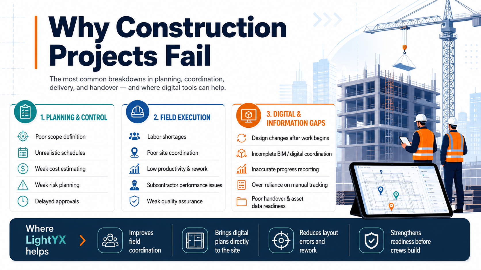
Common Problems in the BIM-to-Shop Drawing Process
Even with BIM, the shop drawing process can fail if project teams do not manage it correctly.
One common problem is using design-level information as if it were construction-ready. A design model may be good enough for coordination or estimating, but not detailed enough for fabrication. If the subcontractor skips detailing and relies too heavily on design intent, errors can carry into procurement and installation.
Another common issue is poor trade coordination. If shop drawings are created independently by each trade without proper BIM coordination, conflicts may only be discovered during installation. At that point, solving them is more expensive and disruptive.
A third issue is unclear review responsibility. The design team reviews shop drawings for conformance with design intent, but the contractor is still responsible for means, methods, fabrication, and installation. If this boundary is misunderstood, teams may assume that “approved” means “fully checked for constructability,” which is not always true.
Version control is another major risk. A project may have multiple versions of design drawings, coordination models, shop drawings, RFIs, submittals, and field markups. If crews use an outdated file, even a well-coordinated drawing can turn into a field error.
Finally, there is the problem of disconnected field execution. A shop drawing may be accurate, but if the information is transferred manually to the field using tape measures, paper drawings, and human interpretation, mistakes can still happen.
That is why the final step — moving from shop drawings to physical execution — is so important.
From Shop Drawings to Physical Execution
Once shop drawings are reviewed, coordinated, and approved, they become the practical source of construction information for the field.
This is where the digital plan meets the jobsite.
For many years, field crews transferred shop drawing information manually. A worker would read a paper drawing or PDF, measure from gridlines or control points, mark locations with chalk or pencil, and then install the work. This process is familiar, but it creates many opportunities for error.
A small interpretation mistake can shift a hanger point. A missed dimension can affect a sleeve location. A wrong reference point can move an entire run of layout. A crew may install based on an older drawing. A trade may lay out work correctly according to its own drawings but still conflict with another trade because the final coordinated information was not used.
This is the “analog gap” between digital coordination and physical construction.
The stronger the shop drawing data, the easier it becomes to close that gap.
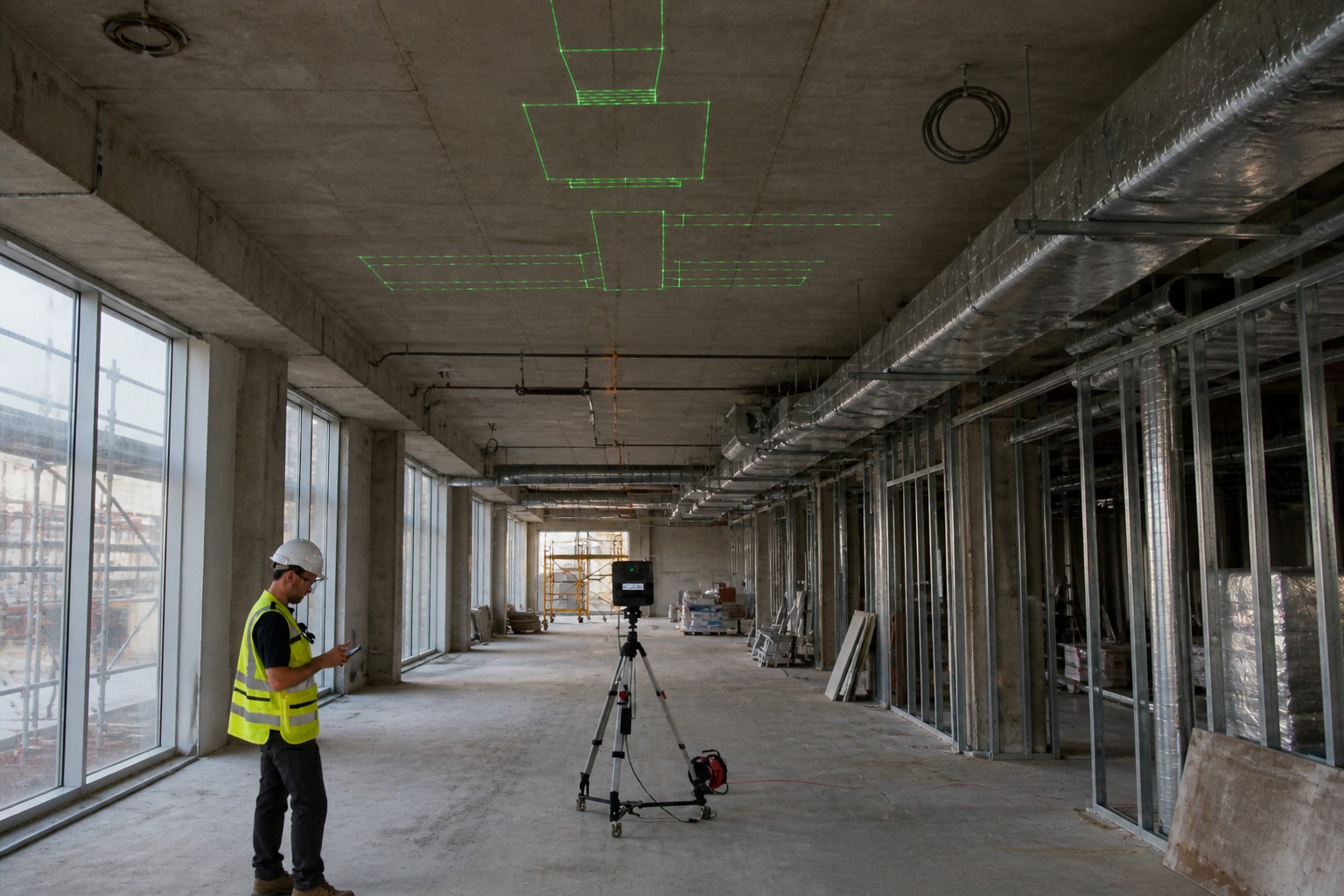
Model-Based Layout and Digital Field Execution
In a modern workflow, approved shop drawing data can be converted into layout points, coordinates, or field-ready geometry. These points may represent anchor locations, hanger points, wall lines, sleeve penetrations, equipment pads, embeds, openings, framing lines, or other installation references.
That data can then be sent to field hardware such as robotic total stations, tablets, or laser projection systems. Instead of manually interpreting the drawing, the field crew works from coordinated digital information.
This is where BIM-to-field workflows become valuable. The goal is not simply to replace paper with a screen. The goal is to reduce the number of times information must be interpreted, redrawn, measured, or manually transferred.
When shop drawings are coordinated and digital field tools can consume that information, the jobsite gets a clearer connection to the approved plan.
The process usually looks like this:
- The design model defines the intent.
- Trade teams develop coordinated shop drawings or fabrication models.
- Layout points or installation geometry are extracted from the approved information.
- Field crews use digital tools to locate the work on the slab, ceiling, wall, or structure.
- Installation happens with less manual interpretation and fewer layout mistakes.
Why This Matters for Contractors
The value of the BIM-to-shop drawing transition is not theoretical. It affects daily construction work.
For MEP contractors, better shop drawings can mean more reliable hanger locations, sleeve penetrations, equipment connections, and prefabricated assemblies.
For drywall and interior contractors, they can mean cleaner framing layout, better coordination around soffits and ceilings, fewer conflicts around openings, and more accurate field installation.
For steel fabricators, they can mean fewer connection errors, better erection sequencing, and more reliable fabrication packages.
For general contractors, they can mean fewer RFIs, fewer clashes, less rework, better trade coordination, and a clearer path from coordination meetings to actual installation.
The key point is simple: field execution is only as good as the information feeding it.
If the shop drawings are incomplete, uncoordinated, or outdated, digital layout tools will not solve the root problem. But when the shop drawings are accurate, coordinated, and construction-ready, digital layout becomes much more powerful because the field crew can execute directly from reliable information.
Where LightYX Fits in the Workflow
LightYX fits into the final stage of this process: turning coordinated construction information into physical layout on the jobsite.
The important point is that LightYX does not replace shop drawings. It depends on them.
The quality of the digital layout depends on the quality of the approved construction information. When shop drawings define the correct wall lines, hanger points, sleeves, anchors, penetrations, or trade-specific installation locations, LightYX can help bring that data directly to the field through full-scale laser projection.
This reduces the need for crews to manually interpret drawings, transfer dimensions, or measure every point from paper. Instead, the approved digital information can be projected directly onto the floor, ceiling, or wall, helping crews work from the same coordinated plan used by the VDC and detailing teams.
This is the practical value of connecting BIM, shop drawings, and field layout. The BIM model creates the digital foundation. The shop drawings make the information buildable. The layout workflow brings that information to the physical jobsite.
Conclusion: BIM Becomes Buildable Through Shop Drawings
BIM is one of the most important tools in modern construction, but a BIM model alone is not automatically construction-ready. Design models communicate intent. Shop drawings translate that intent into the detailed, coordinated, trade-specific information required for fabrication, assembly, and installation.
That transition is where many construction risks are either solved early or pushed into the field.
A strong BIM-to-shop drawing workflow improves coordination, clarifies responsibility, supports fabrication, reduces ambiguity, and gives field crews better information to build from. It also creates the foundation for more reliable digital layout and BIM-to-field execution.
In the modern construction lifecycle, shop drawings are not just a submittal requirement. They are the bridge between digital design and physical construction.
The better that bridge is, the more accurately the project can move from model to shop drawing, from shop drawing to layout, and from layout to the built reality.