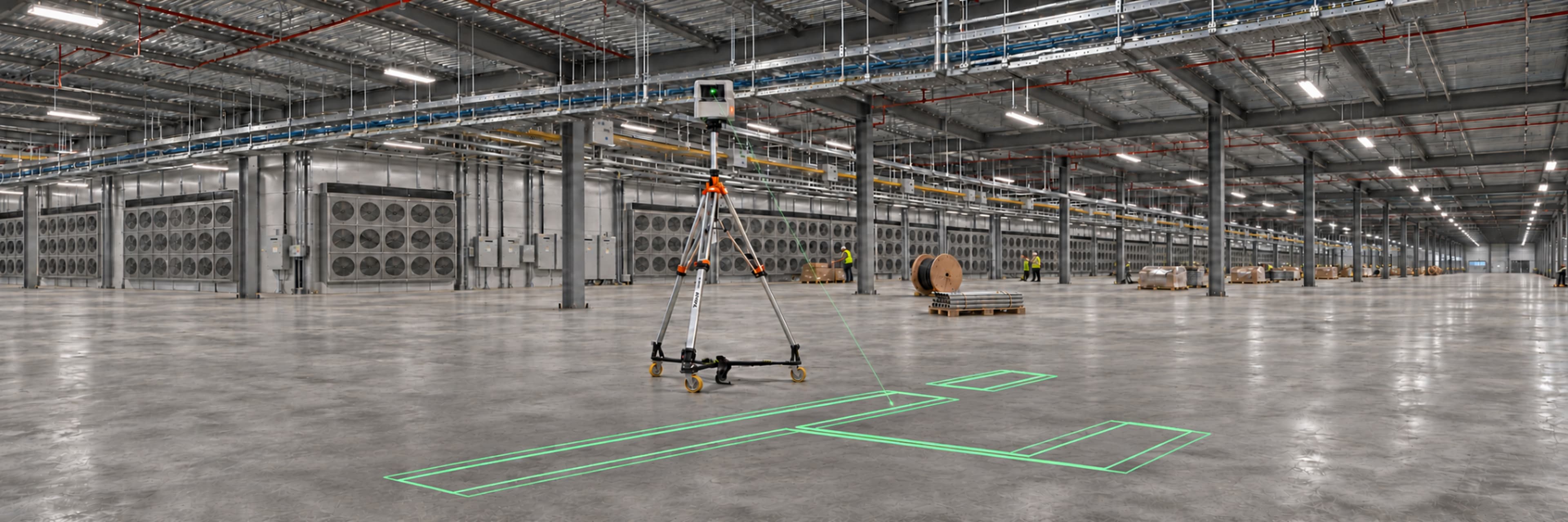
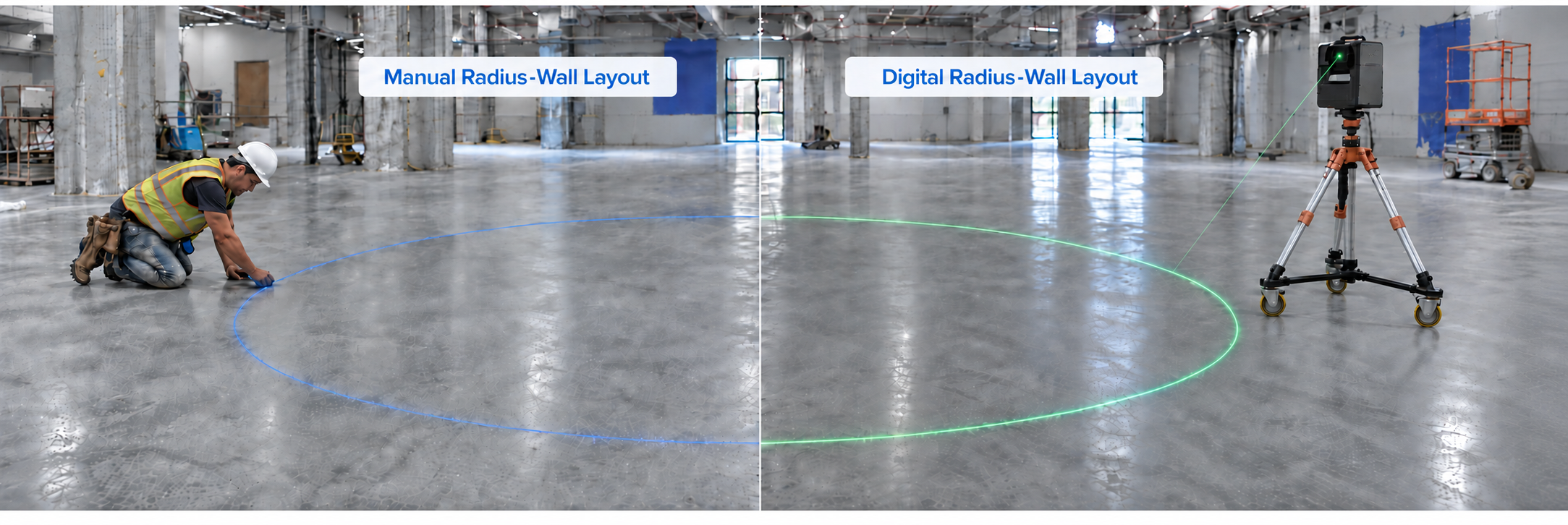
Ceiling Layout in Construction: Hanger Points, Soffits and Overhead Coordination
From hanger points and soffits to overhead coordination, see how digital layout is changing the way ceiling work moves from BIM to the field.

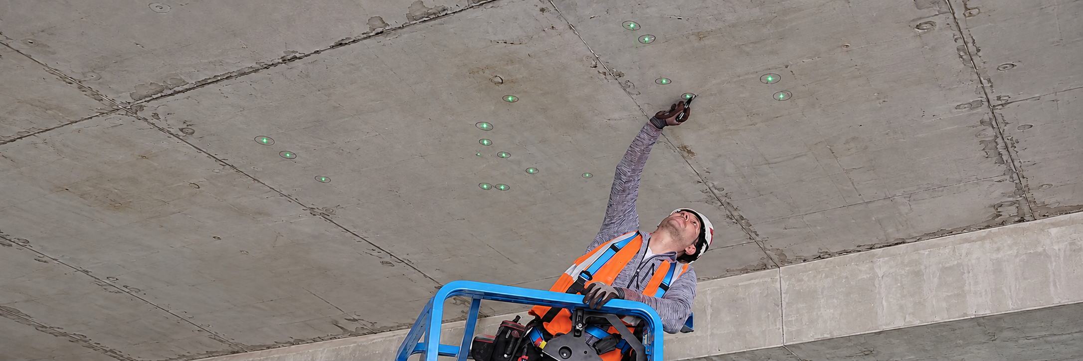
Ceiling layout has one obvious challenge compared with floor layout: the work is above you.
That changes almost every part of the process.
A point that takes seconds to mark on a slab may require a lift when it is on the underside of a deck. A dimension that can be checked directly on the floor may first need to be established below and transferred vertically. And unlike an open slab, the space above a finished ceiling is usually shared by multiple trades.
For ceiling contractors, framing contractors and MEP trades, accurate ceiling layout is therefore not only about locating points. It is about transferring coordinated information into a difficult working environment while maintaining alignment with building control and the systems around it.
Digital BIM-to-field layout is beginning to change how that information reaches the field.
From the Reflected Ceiling Plan to the Field
Much of the visible ceiling design is documented on a Reflected Ceiling Plan, or RCP.
An RCP is a view looking upward at the ceiling. It helps designers and contractors coordinate ceiling elements with walls, rooms and architectural features.
Depending on the project, it may show:
- Lighting fixtures and emergency lighting
- Diffusers, grilles and return-air devices
- Fire sprinklers, smoke detectors and speakers
- Ceiling grid and tile patterns
- Drywall ceilings, soffits and bulkheads
- Ceiling heights, elevation changes and architectural features
But the RCP is not always the complete field layout drawing.
Detailed hanger points, structural attachments, MEP supports, inserts and anchors may instead come from subcontractor shop drawings, fabrication drawings or the coordinated BIM model.
On a modern project, the field team may therefore be working from several coordinated sources. The challenge is turning all of that information into physical locations on the deck or ceiling.
Ceiling Layout Still Starts With Building Control
No matter how detailed the drawings or BIM model are, field layout still needs a reliable connection to building control.
Crews typically work from survey control points, structural grid lines, established wall lines or other approved references. They also need to maintain elevation, because knowing the horizontal location of a ceiling element is only part of the job.
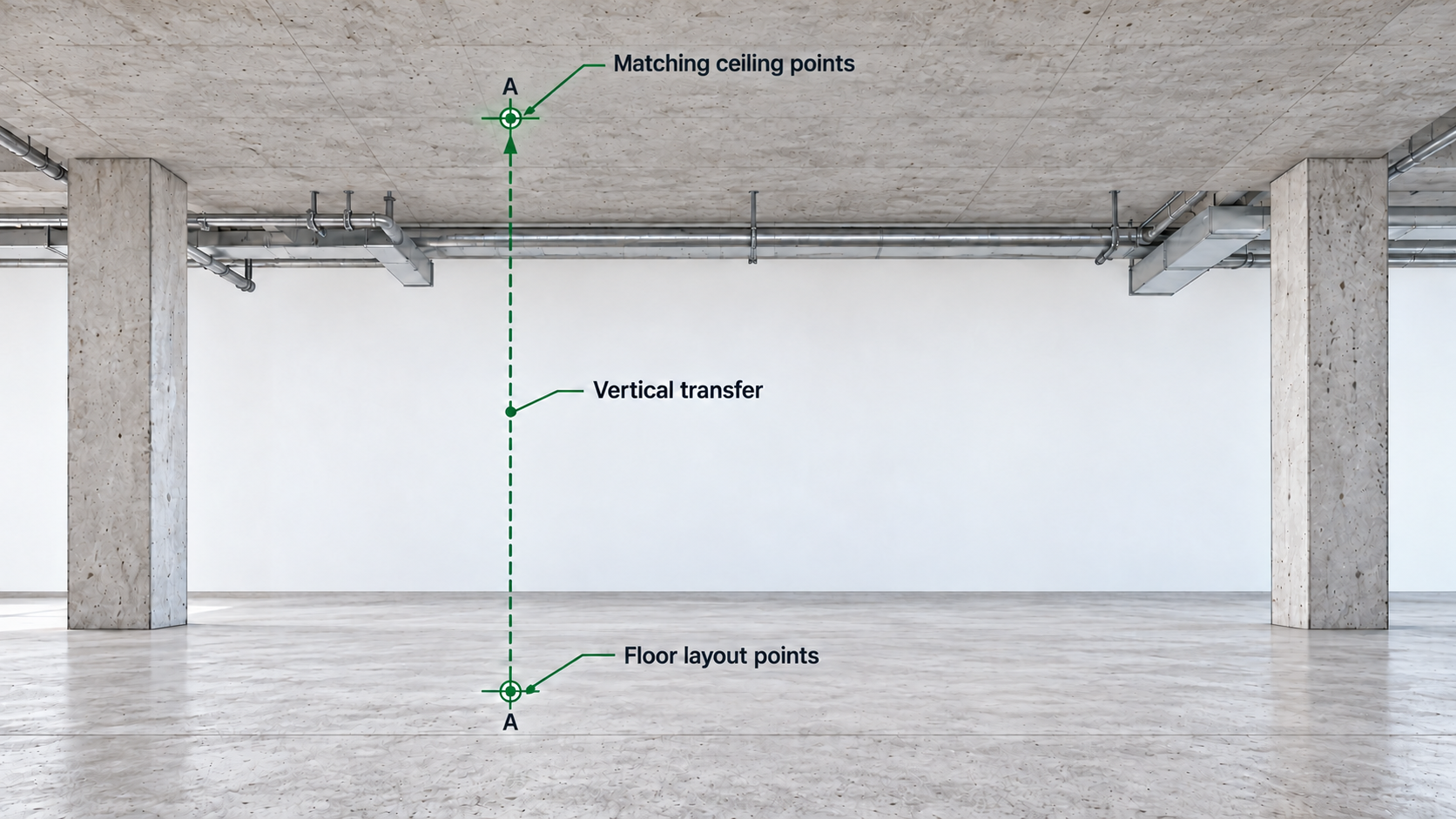
Traditional ceiling layout often begins by establishing references at floor level or around the perimeter of the room. From there, crews measure locations, create control or chalk lines, establish the ceiling grid or hanger pattern and transfer those locations upward.
Historically, a point laid out on the floor could be transferred vertically using a plumb bob. Today, plumb lasers make the same basic process faster.
But the principle remains the same:
Establish the geometry somewhere accessible, then transfer it to where the work will actually be installed.
That additional transfer is one reason overhead layout is inherently more difficult than layout on a slab.
Why Overhead Layout Takes More Time
On the floor, a layout technician can usually walk to a location, mark it and continue.
Overhead, access becomes part of the layout cycle.
A technician may need to move a lift into position, raise the platform, identify the location, mark the deck, lower the lift and reposition before repeating the process.
For one point, that may not seem significant.
For hundreds or thousands of ceiling hanger points or MEP support locations, it can become a major part of the workflow.
Congestion makes it harder. As construction progresses, ductwork, piping, conduit, cable tray, sprinklers and framing begin to occupy the same overhead space. Access becomes more difficult and clear lines of sight to the deck can disappear.
That is why overhead productivity should not be measured only by how quickly a tool can locate one point.
A more useful question is:
How long does it take to complete the entire layout area and make it ready for installation?
From Manual Hanger Layout to Digital Point Layout
A traditional hanger point layout starts from known grid or control lines.
The crew establishes spacing and offsets, measures across the work area, marks locations and periodically checks the work back to control. When locations are first established on the floor, they then need to be transferred to the structure above.
For suspended ceilings, crews also have to establish finished ceiling elevation, main-runner positions and hanger attachment locations.
The process works, but it involves repeated measuring, point transfer and checking.
Robotic total stations, or RTS systems, improve this process significantly.
Once aligned with project control, digital points can be selected from a prepared layout file or model. For overhead work, the instrument can direct a laser to a selected point on the deck. The operator identifies the location, marks it and moves to the next point.
This removes much of the tape measuring, manual calculation and floor-to-ceiling transfer involved in traditional layout.
But the workflow is still generally:
Select a point. Locate it. Mark it. Move to the next point.
For 20 locations, that may not matter much.
For 2,000 hanger points, it does.
For a broader overview of these workflows, see our Guide to Digital Construction Layout.
Hanger Points Show Why Scale Matters
Hanger layout is repetitive by nature.
A large ceiling area can require hundreds or thousands of support points. MEP trades may add thousands more anchors, inserts and hanger locations.
At that scale, productivity becomes less about whether one individual point can be located accurately and more about how efficiently the entire group of points can be transferred to the field.
If a work zone contains 100 hanger points and each one must be found independently, the crew is completing 100 separate layout events.
Overhead, many of those events can also involve moving and repositioning a lift.
If multiple hanger points can instead be displayed together within the same work area, the crew can mark several locations before repositioning.
That is where the difference between point-by-point layout and area-based layout becomes important.
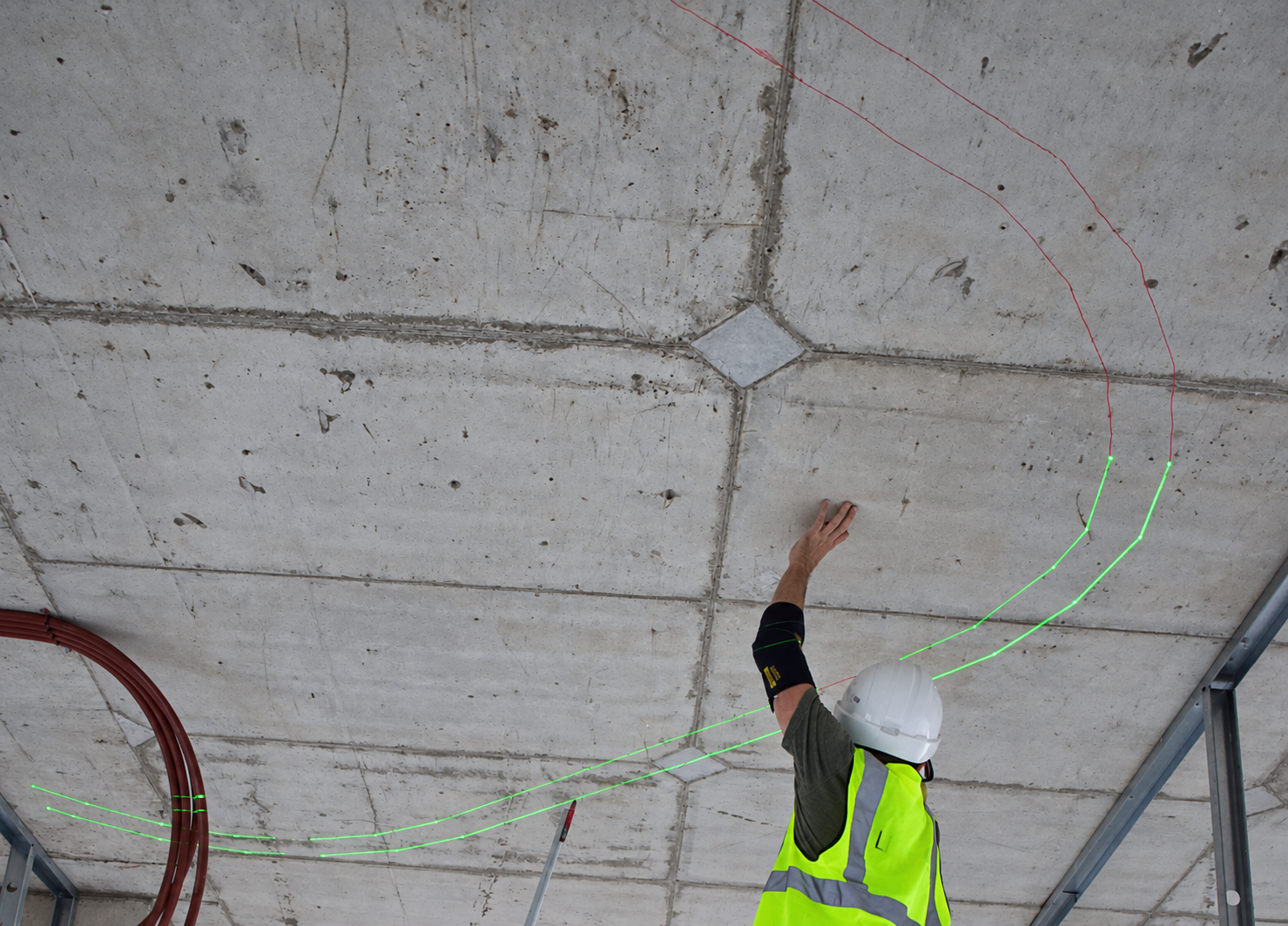
Soffit Layout Is a Geometry Problem
Hanger layout is primarily a point problem.
Soffit layout is often a geometry problem.
Soffits, bulkheads, drywall ceilings, clouds and architectural features contain lines, corners, offsets, curves and changes in elevation.
A soffit may need to align with a wall below, maintain a specific distance from the curtain wall, turn around a column and still avoid ductwork above it.
Traditionally, crews can establish that geometry below and transfer reference points upward.
But as the geometry becomes more complex, reconstructing it from individual measurements or isolated points becomes slower and introduces more opportunities for error.
If the full geometry already exists in CAD or BIM, there is an obvious advantage in bringing that geometry directly to the field instead of rebuilding it manually.
The Ceiling Is Shared Space
The overhead environment is rarely controlled by one trade.
Ceiling framing, ductwork, piping, conduit, cable tray, sprinklers and lighting may all occupy the same limited space above the finished ceiling.
At the visible ceiling plane, the relationship becomes even tighter. Lights, diffusers, sprinklers, speakers, access panels and the ceiling grid all need to align properly with one another and with the architectural layout.
That is why MEP coordination is so closely connected with ceiling work.
BIM coordination may solve many of these relationships before installation begins, but solving them in the model does not automatically solve field execution.
Eventually, that information has to leave the screen and reach the crews installing the work.
That is the BIM-to-field challenge.
For more on that process, see From BIM to Shop Drawings: How Digital Models Become Construction-Ready.
Why Overhead Layout Errors Become Expensive
The cost of a layout error can rise quickly after installation begins.
A wrong mark on the floor can usually be corrected.
A misplaced overhead anchor may already have been drilled. A row of hangers installed from the wrong reference may need to be relocated. A soffit framed several inches from its intended position can interfere with lighting, diffusers or sprinklers.
A ceiling grid shifted from the coordinated RCP can create alignment problems across several trades.
And because overhead construction is so interconnected, the contractor discovering the problem may not be the contractor who created it.
That makes accurate layout an important part of QA/QC before installation begins.
Bringing Full-Scale Digital Layout Overhead
Full-scale laser projection offers another way to transfer coordinated information into the field.
LightYX aligns CAD or BIM information with jobsite control and projects the geometry directly onto floors, walls and overhead surfaces.
For overhead work, that can include ceiling hanger points, main-runner references, ceiling grid lines, soffit boundaries, fixture locations, MEP support points and other coordinated geometry.
The important difference is that multiple points and continuous lines can be visible together.
For hanger point layout, crews can mark several visible locations within one work area rather than navigating independently to every point.
For soffit layout, they can see the complete geometry instead of rebuilding it from individual measurements.
For MEP coordination, approved information from several trades can be understood in its actual physical relationship before installation begins.
Read more about Laser Layout and BIM-to-Field Workflows.
What Should Contractors Evaluate in a Digital Layout Tool?
Accuracy matters, but it is only one part of the workflow.
Contractors should also look at:
- How quickly the tool can align to project control
- How much drawing preparation is required
- Whether it can handle both points and linework
- How easily crews can move between work zones
- How revised drawings are brought back into the field
For overhead work, one question is especially important:
How much time is being spent on layout rather than installation?
A digital layout tool that eliminates manual measuring but still requires extensive point-by-point navigation and lift movement may solve only part of the problem.
The objective should be to reduce the work required between the coordinated drawing and the actual installation.
Ceiling Layout Is Really an Information-Transfer Problem
Experienced ceiling, framing and MEP crews already know how to measure.
The greater challenge is transferring thousands of pieces of coordinated information from an RCP, shop drawings and BIM models into a crowded three-dimensional construction environment while maintaining control, elevation and alignment between trades.
Manual layout does this through measurements, control lines and point transfer.
RTS tools replace many of those measurements with digitally calculated individual points.
Full-scale projection takes another approach by bringing groups of points and complete geometry directly to the work surface.
The technology changes, but the objective remains the same:
Get the correct ceiling layout, hanger location, soffit line, ceiling grid and coordinated MEP information into the field before installation begins.
Because overhead, correcting a mistake is almost always harder than identifying it before the first hanger goes in.